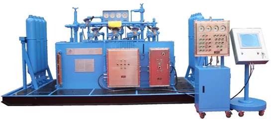
The FKQ series controls the stack, the choke manifold and the kill line, and is licensed under API 16D. Two independent power sources, accumulator bottles sized so a single bottle failure costs at most 25 percent of volume, and an optional nitrogen backup keep the stack operable when pumps or air are lost.
Model designation reads left to right: FKQ series, system pressure in MPa, pump arrangement (D single / S double), recorder type, then the build suffix.
| Model | Stations (total) | Annular | Ram | Choke | Spare | Accumulator (L × bottles) | Theoretical usable (L) | Actual usable (L) | Mounting | Oil tank (L) | Motor (kW) | Electric pump (L/min) | Air pump (ml/stroke) |
|---|---|---|---|---|---|---|---|---|---|---|---|---|---|
| FKQ1440-16 | 16 | 1 | 4 | 7 | 4 | 60×24 | 720 | 504 | Rear | 2600 | 18.5×2 | 46×2 | 165×3 |
| FKQ1920-10 | 10 | 1 | 4 | 4 | 1 | 60×32 | 960 | 672 | Rear | 2300 | 18.5×2 | 46×2 | 165×3 |
| FKQD1280-8 | 8 | 1 | 4 | 2 | 1 | 80×16 | 640 | 496 | Side | 1800 | 18.5×2 | 46×2 | 165×2 |
| FKDY320-4 | 4 | 1 | 2 | 1 | — | 40×8 | 160 | 128 | Side | 920 | 15 | 35 | 165 |
| FKDQ1200-9 | 9 | 1 | 3 | 3 | 2 | 60×20 | 600 | 420 | Rear | 2200 | 18.5×2 | 46×2 | 165×3 |
| FKDQ1200-9B | 9 | 1 | 3 | 4 | 1 | 60×20 | 600 | 420 | Rear | 2200 | 18.5×2 | 46×2 | 165×3 |
| FKDQ960-7 | 7 | 1 | 3 | 2 | 1 | 60×16 | 480 | 336 | Rear | 2200 | 18.5×2 | 46×2 | 165×2 |
| FKDQ960-7B | 7 | 1 | 2 | 4 | — | 60×16 | 480 | 336 | Rear | 2200 | 18.5×2 | 46×2 | 165×2 |
| FKDQ800-7 | 7 | 1 | 3 | 2 | 1 | 40×20 | 400 | 320 | Side | 1330 | 18.5×2 | 46×2 | 165×2 |
| FKDQ800-7A | 7 | 1 | 3 | 2 | 1 | 40×20 | 400 | 320 | Side | 1330 | 18.5×2 | 46×2 | 165×2 |
| FKDQ640-7 | 7 | 1 | 3 | 2 | 1 | 40×16 | 320 | 256 | Rear | 1660 | 18.5 | 46 | 165×2 |
| FKDQ640-6 | 6 | 1 | 3 | 1 | 1 | 40×16 | 320 | 256 | Side | 1160 | 18.5 | 46 | 165×2 |
| FKDQ640-6A | 6 | 1 | 3 | 1 | 1 | 80×8 | 320 | 248 | Side | 1160 | 18.5 | 46 | 165×2 |
| FKDQ480-5 | 5 | 1 | 3 | 1 | — | 40×12 | 240 | 192 | Side | 1160 | 18.5 | 35 | 165×2 |
| FKQ1440-14 | 14 | 1 | 4 | 7 | 2 | 60×24 | 720 | 504 | Rear | 2300 | 18.5×2 | 46×2 | 165×3 |
| FKQ1280-12 | 12 | 1 | 3 | 1 | 7 | 80×16 | 640 | 496 | Side | 2400 | 18.5×2 | 46×2 | 165×3 |
| FKQ1440-10 | 10 | 1 | 5 | 2 | 2 | 80×18 | 720 | 558 | Side | 2150 | 18.5×2 | 46×2 | 165×3 |
| FKQ1280-10 | 10 | 1 | 4 | 4 | 1 | 80×16 | 640 | 496 | Side | 2150 | 18.5×2 | 46×2 | 165×3 |
| FKQ1200-10 | 10 | 1 | 4 | 4 | 1 | 60×20 | 600 | 420 | Side | 2150 | 18.5×2 | 46×2 | 165×3 |
| FKQ1200-9 | 9 | 1 | 3 | 3 | 2 | 60×20 | 600 | 420 | Rear | 2200 | 18.5×2 | 46×2 | 165×4 |
Accumulator figures are bottles × unit volume; usable volumes assume the pre-charge stated in the factory sheet. Configurations outside this list are built to order.
Translated from the BOP Control System datasheet issued by BOMCO. Figures are factory values in SI units; the quotation confirms the exact build for your order.
We build BOP Control System in Baoji and test each unit against the figures above before it leaves the works. Our engineers set the rating point at commissioning to suit your fuel, altitude and ambient conditions, and we hand over the signed test sheet with the unit.
Tell us the duty you have in mind for BOP Control System and we will confirm which row of the table applies, or quote a special build when none of them fits.
Two independent power sources with electric, pneumatic or manual pumps to match the site. That is the detail a catalogue listing usually leaves out, and the one that decides whether the unit suits the well in front of you.
Our control units are function tested with the accumulator set as installed, and the test sheet goes to site with the unit.
The BOP accumulator unit sits inside the FKQ package: bottles, pumps, manifold and the gauges the driller reads at the console.
Bottles are sized so that a single bottle failure costs at most a quarter of the usable volume, which is what keeps the stack operable after a fault.
Well Control
Wellheads